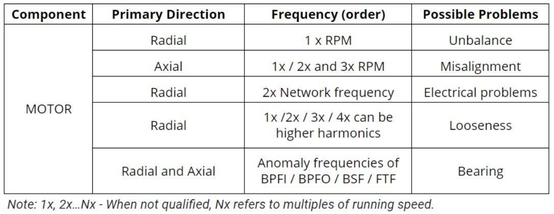
Conveyor Belt

Conveyor belts are widely used in the transportation and material movement in diverse production processes. Generally, the equipment has a constant flow, moving materials from one point to another of the production process. The equipment is basically composed of motors, gearboxes, pulleys and their respective bearing casings.

The motor is responsible for activating the machinery that, due to its low operation speed and high loads, requires a coupled gearbox. Motors and gearboxes have already been specifically addressed before, so we will give more attention to the conveyor belt pulleys in this article.


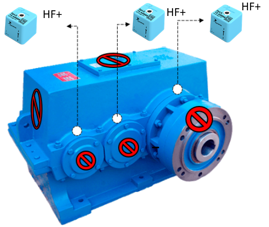
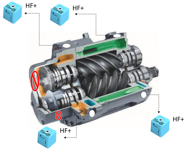
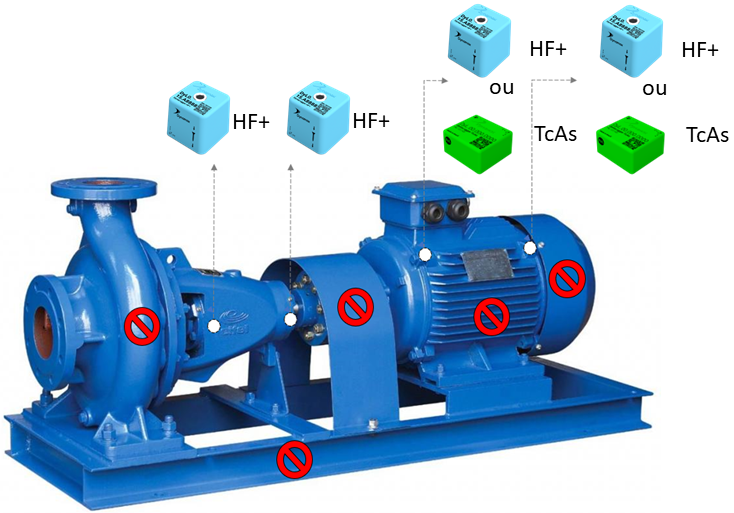
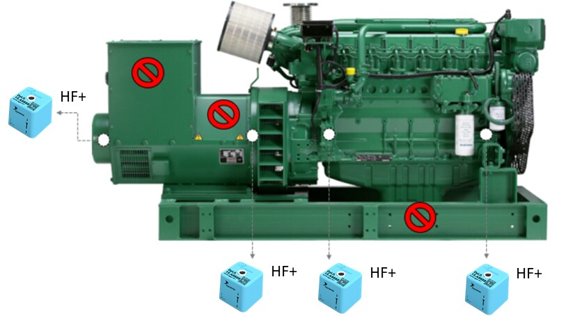
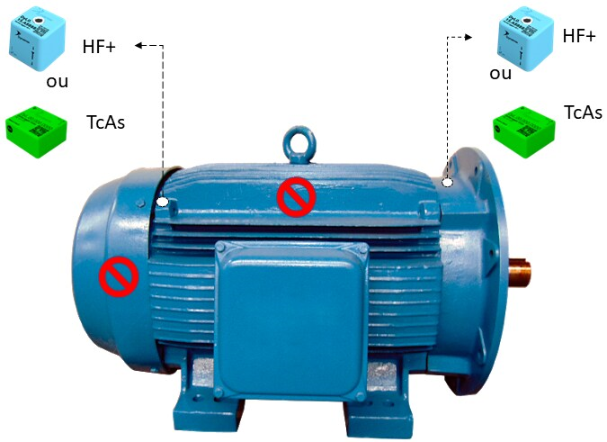
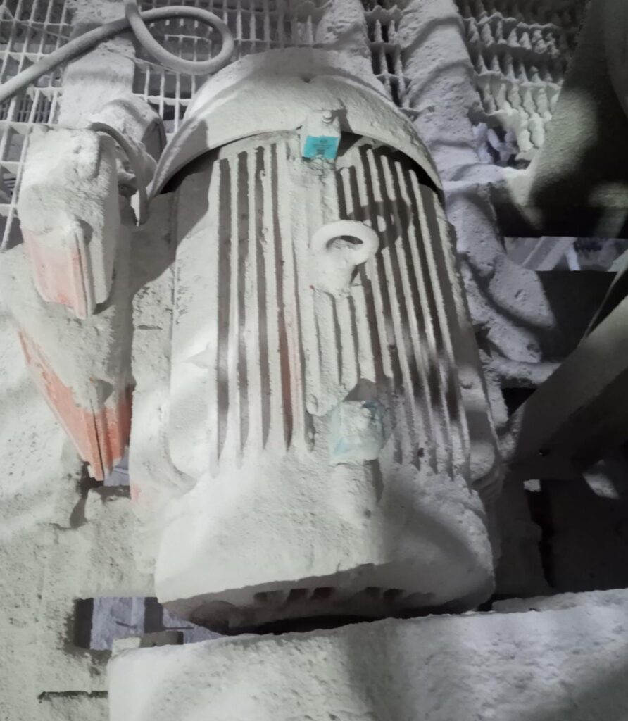
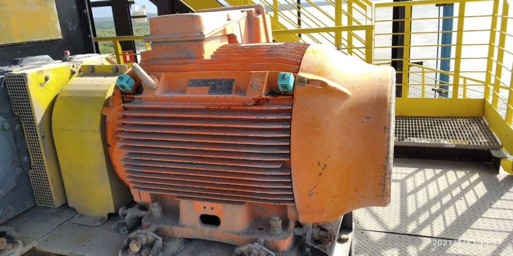
Figure 1: Positioning and sensor model  indication for motors and gearboxes
 

The pulleys are responsible for activation, return, stretching and belt back, depending on their position on the equipment.  All pulleys are fixed to the equipment structure by means of bearing housings. The bearing housings, in turn, consist basically of bearings, bushings and nuts, and can be manufactured with a variable number of rolling elements, sizes, formats, etc. 

Keeping  bearing casings in good operating condition is an essential task for safety  and good performance of the production process.  The most common bearing failure modes are linked to the following causes:

  • Handling and transport;
  • Assembly errors;
  • Excessive stresses and loads;
  • Misalignments;
  • Inefficient lubrication;
  • Inefficient sealing.

These faults can generate defects in the cage, balls or rollers, inner and outer races.

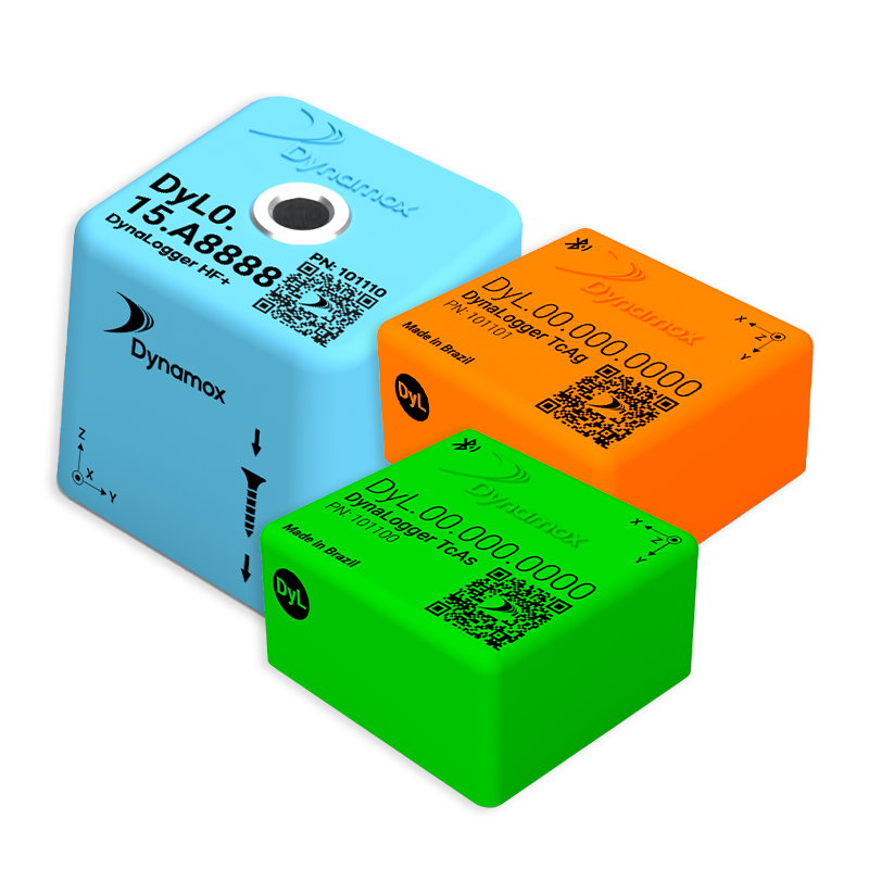
These defects are identified through predictive maintenance, using vibration analysis. Two sensor models can be used to successfully monitor pulley bearings: 1) DynaLogger TcA+ with maximum frequency of 1KHz and 2) DynaLogger HF with maximum freq. of 6.4 KHz. Both models are IP66 and IP68 certified, being impermeable to dust and resistant to liquids, making it possible to install near the belt.  The sensor must be placed parallel to the rotation axis, and avoiding flexible bases and covers.


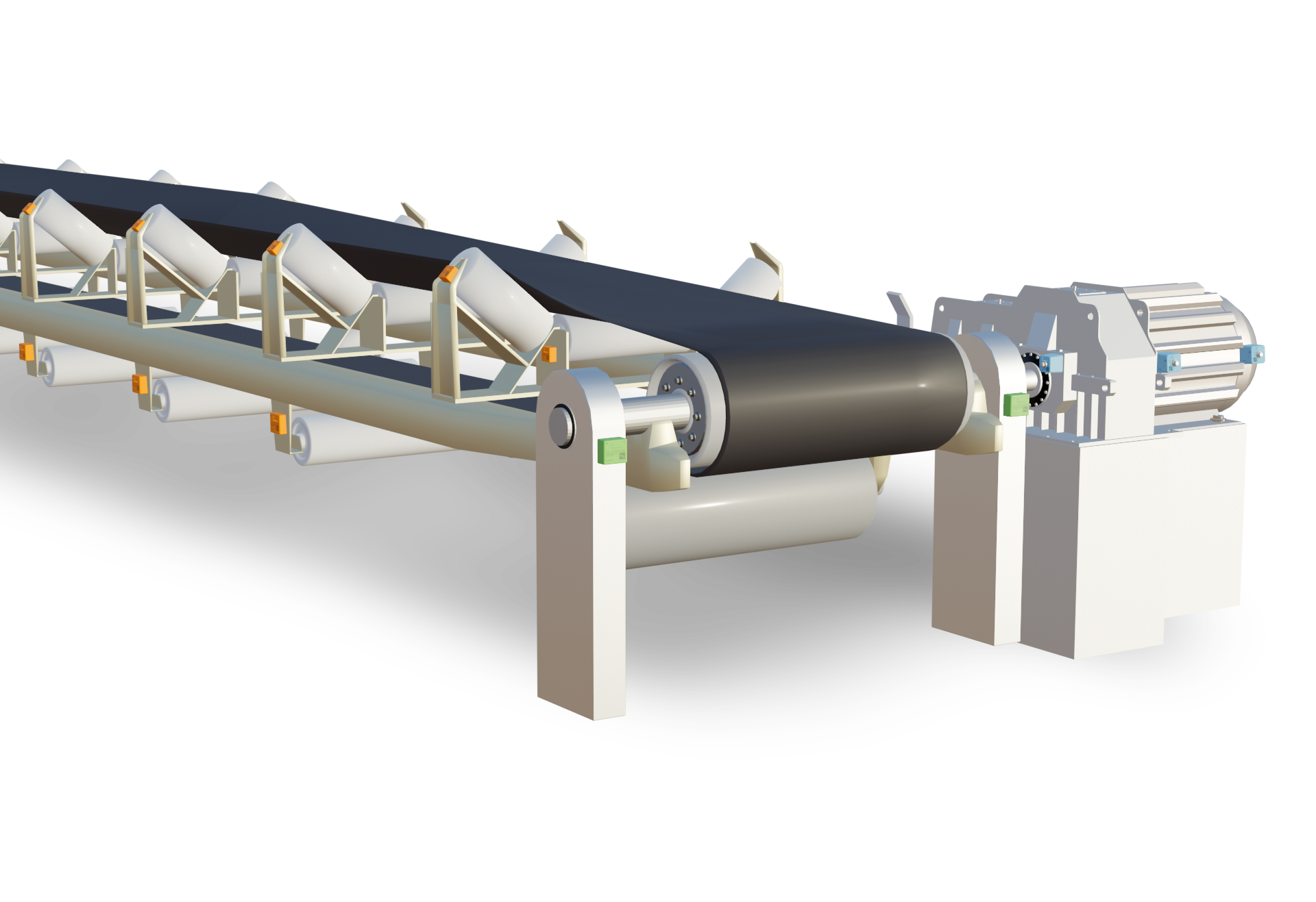
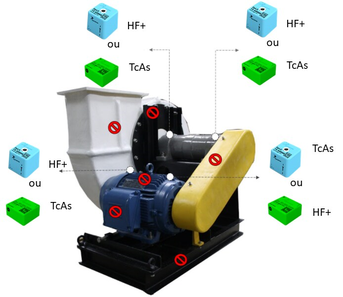
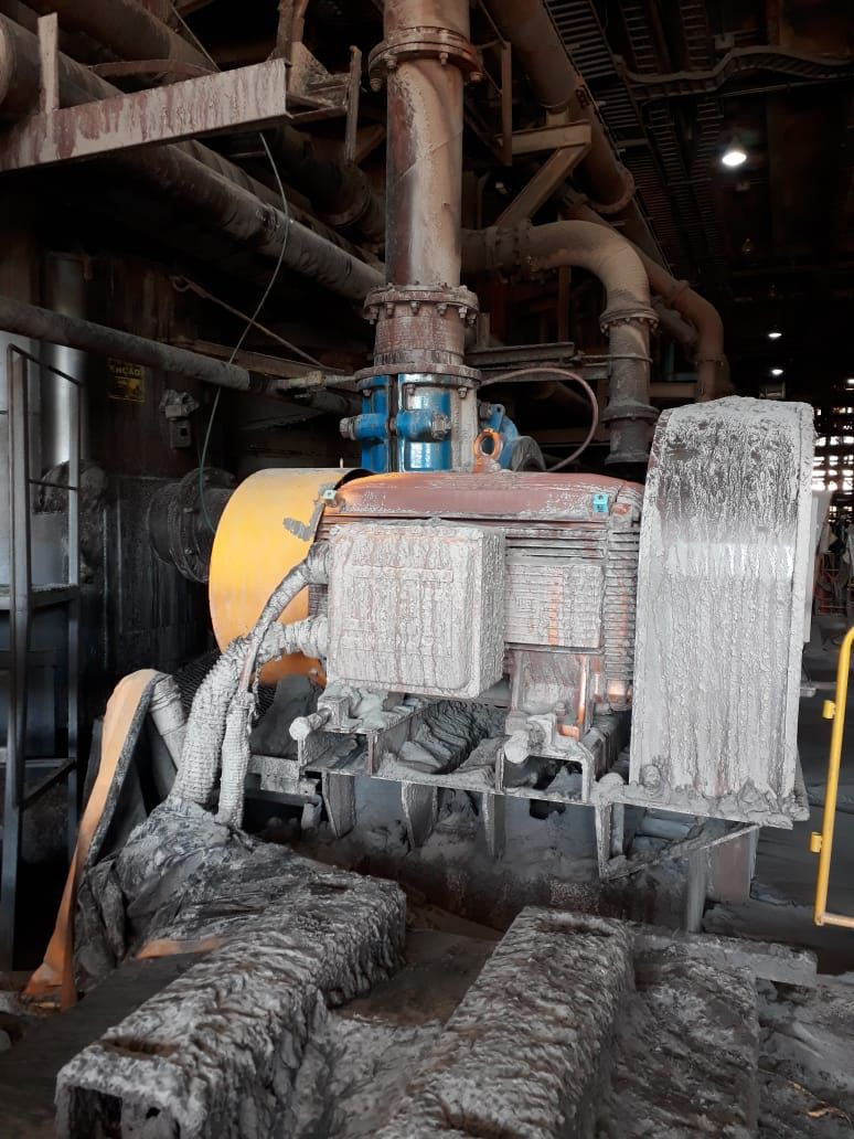
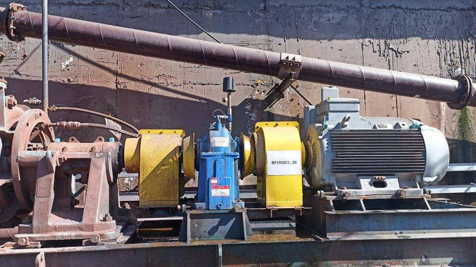
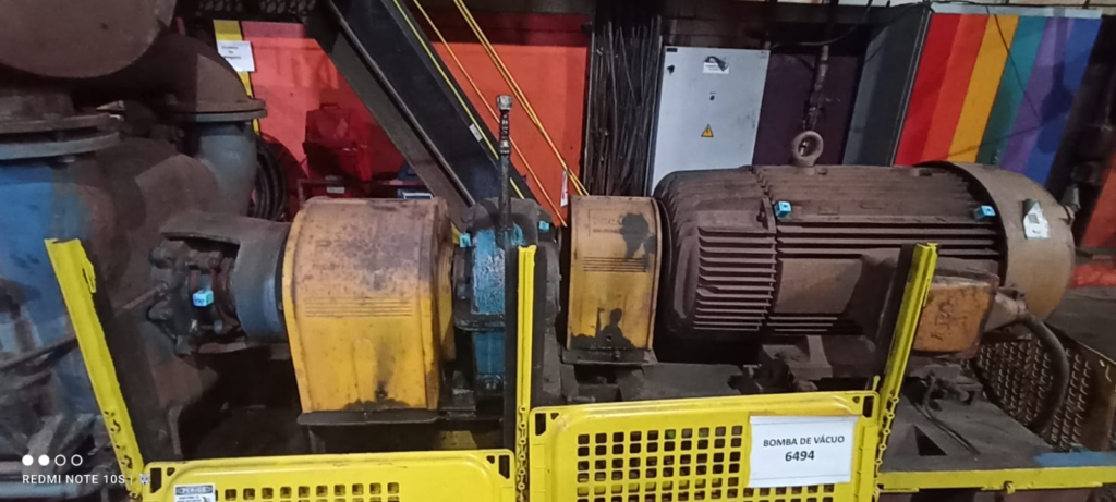
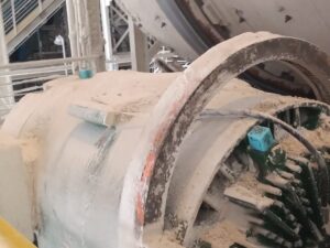
Figure 2: Conveyor belt and bearing housing of the drive pulley in detail


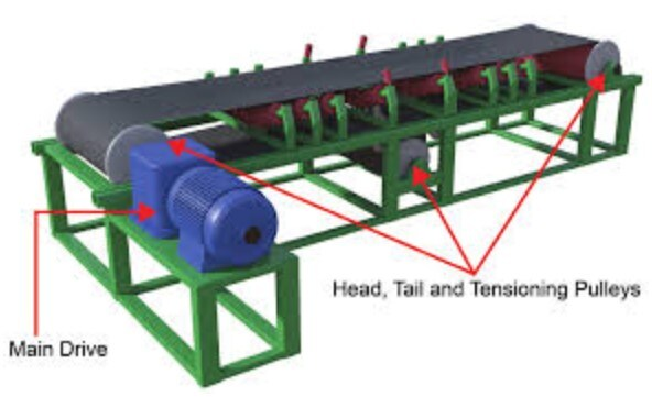
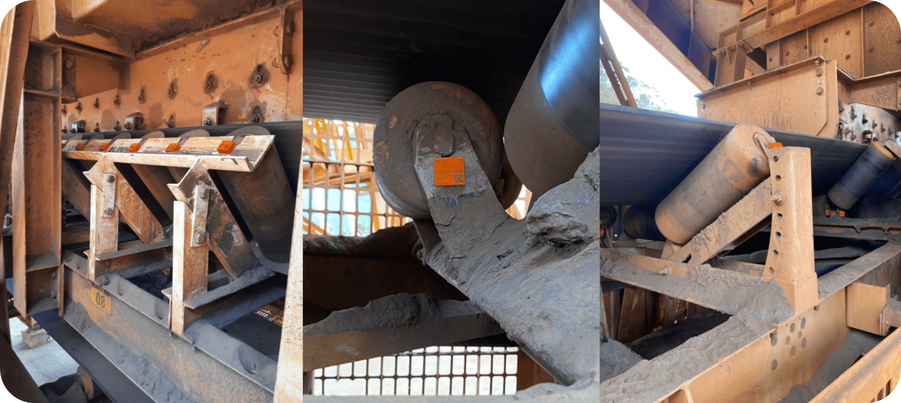
Figure 3: Conveyor schematic with application of DynaLoggers HF sensors in pulley bearing housing
 

In order to demonstrate the good use of sensors in conveyor belt pulleys let’s take a brief example.

Example: Fault monitoring appearing in the frequency of the outer race (highlighted in the green lines) of the 23152 CCK/W33 bearing with 84 RPM.


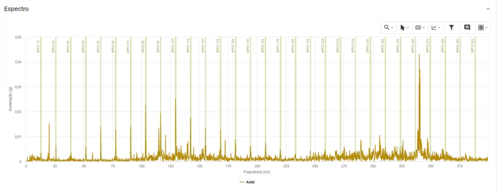
Figure 4: Fault spectra on bearing outer race

Compressor

Compressors are widely used in industrial processes to compress air and other types of gases. These machines have a wide range of applications in industries, going from compressed air supply for general applications to very specific ones, such as cooling of cold rooms in food processing industries. As equipment that generally work with high speeds and small clearances between its components, constant monitoring of this type of machine is recommended and can assist in anticipating potential faults.

One of the predictive techniques that can be used for compressor monitoring is vibration analysis. Manufacturers commonly inform the monitoring spots on this type of machine. In general, the monitoring spots are indicated on the compressor input shaft (as close as possible to the gears and bearings), as shown in the figure below. DynaLoggers HF sensors are the most recommended for this task, since the compressors generally operate at high speed and their faults usually appear at higher frequencies. If vertical mounting is not possible, horizontal spots can be chosen.


Gearbox

Gearboxes are used to increase or decrease the speed of a drive system or simply change the direction of rotation. A variety of problems in this type of system can be detected by vibration analysis, such as:

  • Gear teeth wear
  • Excessive load on teeth
  • Gear eccentricity and / or looseness
  • Cracked or broken gear teeth
  • Hunting tooth problems

One of the main frequencies of interest when evaluating the integrity of the gears will be the gear  meshing frequency (GMF =  number of teeth X RPM), mainly monitoring the frequency amplitude increase and the relationship with its harmonics. However, it is important to note that the GMF, by itself, is not a fault or defect frequency. All gears generate frequencies of a certain amplitude. In addition, all gearing frequencies have sidebands of some amplitude. Thus, the analysis must be based on prior knowledge of the breadth of healthy machinery and must be carefully analyzed by vibration analysts.

More specifically, a reduction set is composed of 4 main components 

  • axes: the amount of which depends on the number of gears,
  • gears: whose relations of number of teeth and reduction or increase ratio in the rotation speed, 
  • bearings: allow the shaft ends to not wear out and 
  • housing: houses all these elements. 

It is common for analysts and maintenance managers to be concerned with checking vibration data only for the set of gear meshes and often end up ignoring the bearings. However, in the event that one of the bearings fails, the entire system will be compromised, possibly even causing damage to the gear set.

With the implementation of the Dynapredict Solution, it is possible to continuously monitor the amplitude evolution in the frequencies connected to the GMF , as well as bearing defects. In order to have greater precision and reliability of the acquired data, it is recommended to install the DynaLogger HF sensor model in each bearing present in the gearbox. Still with regard to sensor mounting, it is indicated to avoid sensor positioning on screwed covers and preferably choose rigid spots at the housing, always as close as possible to the element to be monitored.


(Sensors shall be mounted on both sides of the equipment)


Table 1 – Typical fault frequency and its causes


Fans and Blowers

Blowers and fans are equipment used for ventilation, aeration, exhaustion, cooling and drying in various production processes in the most varied industries.

The fans are subject to forces generated by their operating speed, static pressures and system arrangement. These forces, called operational forces, cause forced vibrations and can originate from the rotating parts themselves. Unbalanced fan wheels and driving pulleys are examples of forces that can cause unbalance and misalignment. Another example is the axial load on the fan bearings, which is mainly generated by the negative static pressure at the inlet of the fan blades.

Due to the process in which this type of system is used, the most common fault modes are: unbalance, misalignment, eccentric pulleys, looseness and belts wear and structural looseness, identified at low frequencies. Also, some bearing problems, especially premature wear and tear generated by the fault modes mentioned above, can occur.

The DynaLogger TcAs, with its frequency range up to 2.5 kHz, is capable of identifying the mentioned faults, but the detection of bearing faults will occur at a more advanced stage. For detection in earlier stages and also for lubrication faults or electrical faults related to the rotor and stator, it is recommended to use the DynaLogger HF+ due to its larger frequency range, up to 13 kHz.

It is important to mount DynaLoggers on all bearing housings or rigid parts for effective monitoring. Avoid mounting sensors on flexible surfaces, on curves or that have localized resonance such as protective covers and fins.


Table1 – Typical fault frequency and its causes


Centrifugal Pumps

Centrifugal pumps are hydraulic machines, which consist usually of rotating elements (e.g., pump impeller, bearings, electric motor) and stationary elements (volute/casing, diffuser, stay/guide vanes, and housing bearing), which can generate fault frequencies from mechanical and hydrodynamic sources. Mechanical sources are generated by the rotation of unbalanced masses and friction in the bearings. Hydrodynamic vibration, on the other hand, is usually caused due to flow disturbances, generated by the interaction of the rotor blades, particularly with the volute and / or guide vanes.

To predictively monitor the vibration and temperature parameters, two models of sensors can be used
DynaLogger HF+ and  DynaLogger TcAs 

The DynaLogger TcAs model can be used specifically in motors, where it will be used to identify structural defects, looseness, electrical faults and stage 3 bearing defects. In the Pump bearings, due to the faults high frequencies, the use of the DynaLogger HF+ is indicated. The number of sensors is directly linked to the number of bearings and the mechanical seal. Always try to mount the sensors as close as possible to the bearings, avoiding noisy signals and flexible parts, which can increase the reliability of the analysis.


Table 1 – Typical fault frequency and its causes


Here are pictures of actual installations of the sensors:


Generators

The main purpose of generator sets is to provide electrical energy, continuous or temporary (in cases of emergency), safely and effectively. The generator sets serve not only to supply energy to unsupported regions, but also to be activated in cases of emergency, avoiding various losses due to power outage.

Small generators generally use common rotating elements, in which case the vibration behavior and fault diagnosis is similar to that of a large electric motor. The vibration data measurement requirements for diesel powered generators should normally be in accordance with ISO 10816 part 3.

Measurements must be made on each bearing housing and on the crankshaft bushings. Avoid mounting sensors on the protective covers or at the equipment base. The frequency range must be enough to cover from 2 Hz to at least 2x the frequency of the fanspeed, with a minimum range  up to 2 kHz, according to ISO 10816. Therefore, for the monitoring of diesel generators, it is recommended to use the DynaLogger HF+ model, due to its high spectral range that can reach up to 13 kHz for uniaxial and triaxial measurements.


Electric Motors

How to monitor electric motors with the DynaPredict Solution:

Electric motors are responsible for the operation of the majority of industrial equipment to generate movement. Failures in this component may cause a halt in production as well as accidents.

Monitoring operational conditions is an important activity in the search for reliability of these assets.

Dynamox’s sensors allow for the online monitoring of parameters such as vibration and temperature which allow for the identification of potential defects and planned interventions, thereby reducing production downtime and increasing the efficiency of the production process as a whole.

Regarding the position of sensors at an electric motor, it is recommended the monitoring be done either from the drive end (DE) or non-drive end (NDE) as shown in the image below.

OBS: the NDE spot may offer certain challenges to the sensor mounting, because of the protective cover. If necessary, consider drilling a hole or cutting a notch in the cover to allow access to a rigid mounting location. Never install sensors on the motor terminal or cooling fins, which are parts that emit high levels of vibration and make fault analysis difficult.

Regarding this equipment, two types of sensors can be used:

  •  DynaLogger HF+. A sensor with a maximum frequency of 1300 Hz. This sensor is recommended for motors coupled to equipment of most importance. Due to its high frequency range, it is possible to identify early stage bearing or lubrication defects, as well as faults in the rotation frequency of the machine, such as with the TcAs.
  • DynaLogger TcAs . A Sensor with a maximum frequency around 2500Hz, which is recommended for low to medium criticality machines that do not present a history of bearing or lubrication related failures, since these defects may usually appear at higher frequencies. These sensors allow for the detection of faults in the rotational frequency of the machine, such as unbalance, misalignment, looseness and others. Besides,  this sensor can be useful to detect bearing defects in the later stage.


For the DynaLogger mounting, there are two main alternatives: studor adhesive mounting. See more details here under item 4.

Regarding defects,  the following root causes related to the machine problems, in terms of the axis and its characteristic frequencies, are indicated below:

 
Images of sensor installations:

A Good Practice Guide to Placing Sensors in Machines

The following sections will present best practices in the positioning of Dynamox vibration and temperature sensors for typical industrial machinery, such as motors, pumps, compressors, exhaust fans, etc.

The objective of the guide is to assist the user in choosing a suitable location for installation of the sensors, helping to obtain reliable and quality data that allows an effective predictive analysis.

The guide will also indicate which sensor best applies to each machine, focusing on the following models:

DynaLogger HF + : Triaxial temperature and vibration monitoring with a maximum frequency of 13000 Hz, performing telemetry and spectral analysis
DynaLogger TcAs : Triaxial vibration and temperature monitoring with frequency up to 2500 Hz, performing telemetry and spectral analysis
DynaLogger TcAg : Triaxial vibration and temperature monitoring with a maximum frequency of 2500 Hz. 

NOTE: The information contained in these sections are only recommendations and should not be taken as positioning rules.

1. Introduction

The complete solution includes:

• DynaLogger, with vibration and temperature sensors and internal memory for data storage. The device is certified for zone 0 explosive atmospheres, according to INMETRO certification;

• Application, for data collection, action and analysis on the shop floor;

• Web Platform, with historic data and diagnostic tools for data analysis.

In addition, a DynaGateway could be added to the solution in order to automate data collection from the DynaLoggers and send the data directly to the Web Platform.


 The flowchart below shows a basic step-by-step outline of how the solution works: