Conveyor Belt
Conveyor belts are widely used in the transportation and material movement in diverse production processes. Generally, the equipment has a constant flow, moving materials from one point to another of the production process. The equipment is basically composed of motors, gearboxes, pulleys and their respective bearing casings.
The motor is responsible for activating the machinery that, due to its low operation speed and high loads, requires a coupled gearbox. Motors and gearboxes have already been specifically addressed before, so we will give more attention to the conveyor belt pulleys in this article.
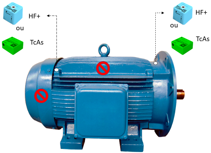
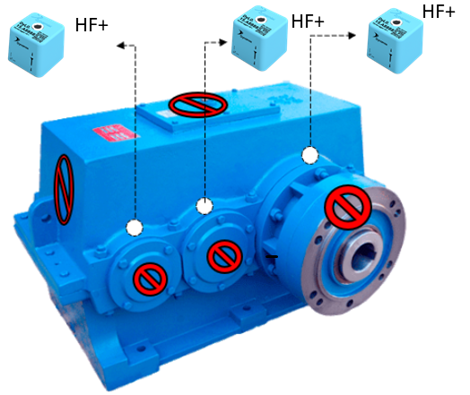
Figure 1: Positioning and sensor model indication for motors and gearboxes
The pulleys are responsible for activation, return, stretching and belt back, depending on their position on the equipment. All pulleys are fixed to the equipment structure by means of bearing housings. The bearing housings, in turn, consist basically of bearings, bushings and nuts, and can be manufactured with a variable number of rolling elements, sizes, formats, etc.
Keeping bearing casings in good operating condition is an essential task for safety and good performance of the production process. The most common bearing failure modes are linked to the following causes:
- Handling and transport;
- Assembly errors;
- Excessive stresses and loads;
- Misalignments;
- Inefficient lubrication;
- Inefficient sealing.
These faults can generate defects in the cage, balls or rollers, inner and outer races.
These defects are identified through predictive maintenance, using vibration analysis. Two sensor models can be used to successfully monitor pulley bearings: 1) DynaLogger TcA+ with maximum frequency of 1KHz and 2) DynaLogger HF with maximum freq. of 6.4 KHz. Both models are IP66 and IP68 certified, being impermeable to dust and resistant to liquids, making it possible to install near the belt. The sensor must be placed parallel to the rotation axis, and avoiding flexible bases and covers.
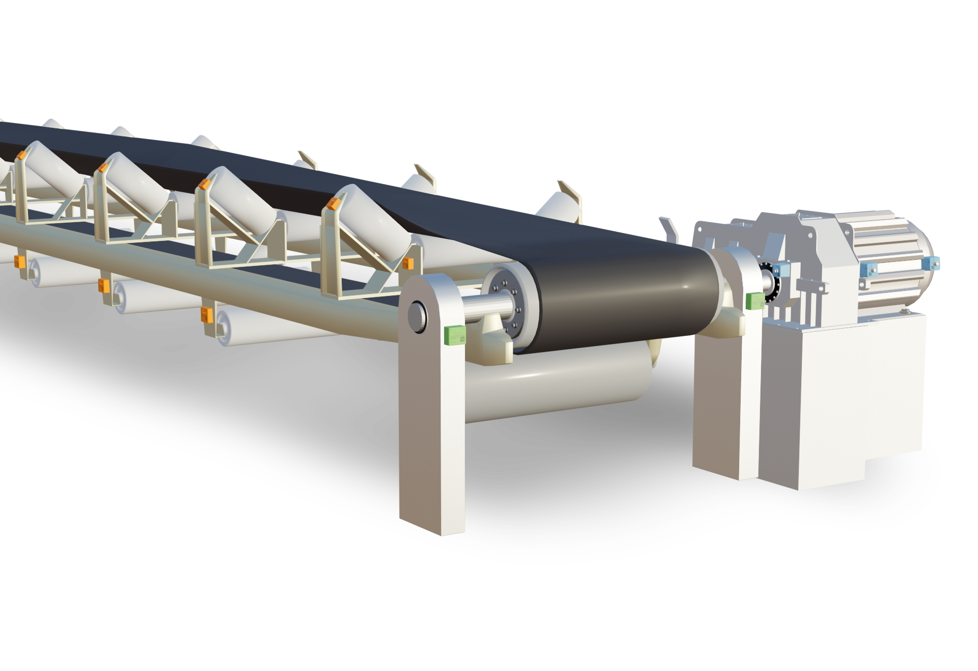
Figure 2: Conveyor belt and bearing housing of the drive pulley in detail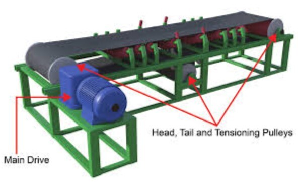
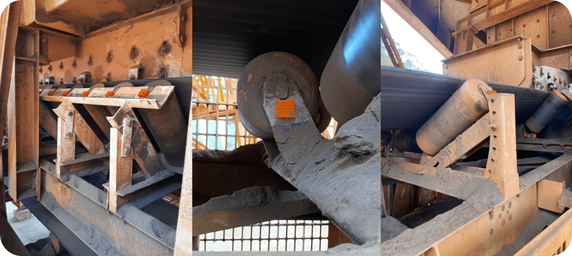
Figure 3: Conveyor schematic with application of DynaLoggers HF sensors in pulley bearing housing
In order to demonstrate the good use of sensors in conveyor belt pulleys let’s take a brief example.
Example: Fault monitoring appearing in the frequency of the outer race (highlighted in the green lines) of the 23152 CCK/W33 bearing with 84 RPM.
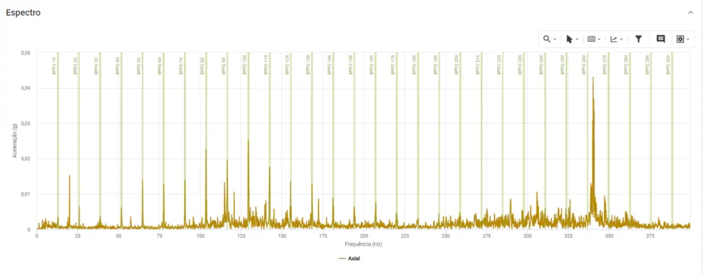
Figure 4: Fault spectra on bearing outer race