Gearbox
Gearboxes are used to increase or decrease the speed of a drive system or simply change the direction of rotation. A variety of problems in this type of system can be detected by vibration analysis, such as:
- Gear teeth wear
- Excessive load on teeth
- Gear eccentricity and / or looseness
- Cracked or broken gear teeth
- Hunting tooth problems
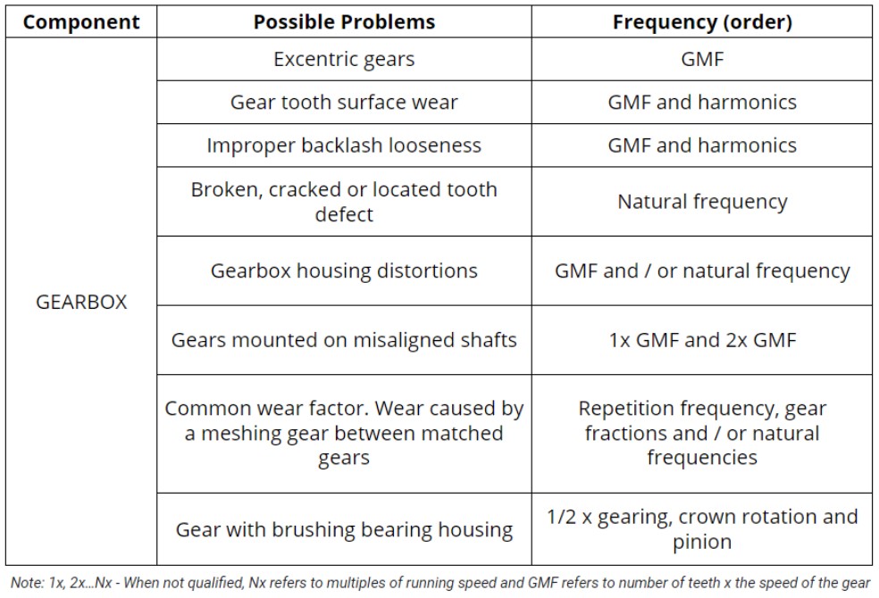
One of the main frequencies of interest when evaluating the integrity of the gears will be the gear meshing frequency (GMF = number of teeth X RPM), mainly monitoring the frequency amplitude increase and the relationship with its harmonics. However, it is important to note that the GMF, by itself, is not a fault or defect frequency. All gears generate frequencies of a certain amplitude. In addition, all gearing frequencies have sidebands of some amplitude. Thus, the analysis must be based on prior knowledge of the breadth of healthy machinery and must be carefully analyzed by vibration analysts.
More specifically, a reduction set is composed of 4 main components
- axes: the amount of which depends on the number of gears,
- gears: whose relations of number of teeth and reduction or increase ratio in the rotation speed,
- bearings: allow the shaft ends to not wear out and
- housing: houses all these elements.
It is common for analysts and maintenance managers to be concerned with checking vibration data only for the set of gear meshes and often end up ignoring the bearings. However, in the event that one of the bearings fails, the entire system will be compromised, possibly even causing damage to the gear set.
With the implementation of the Dynapredict Solution, it is possible to continuously monitor the amplitude evolution in the frequencies connected to the GMF , as well as bearing defects. In order to have greater precision and reliability of the acquired data, it is recommended to install the DynaLogger HF sensor model in each bearing present in the gearbox. Still with regard to sensor mounting, it is indicated to avoid sensor positioning on screwed covers and preferably choose rigid spots at the housing, always as close as possible to the element to be monitored.
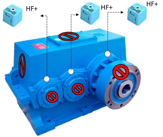
(Sensors shall be mounted on both sides of the equipment)
Table 1 – Typical fault frequency and its causes